
TM 5-5420-226-20-2
FUEL-WATER SEPARATOR OPERATIONAL TESTS (Sheet 4 of 11)
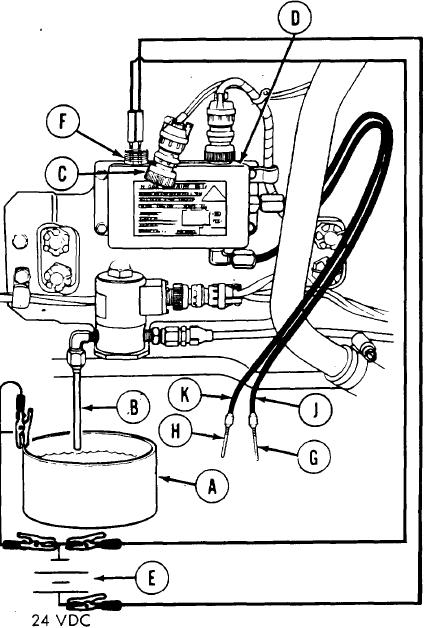
Automatic Drain Test (Sheet 1 of 2)
Fill xnetal container (A) with water.
1.
2. Place metal container (A) under
drain line solenoid drain valve drain
tube (B).
Using pliers, disconnect engine
3.
electrical harness connector (C)
from fuel-water separator control
box (D) by turning counterclockwise.
.
4.
Connect jumper wires from negative
terminal-of power source (E) to metal
cent airier (A).
NOTE
In order to perform steps 5 and 6, two leads,
similar to multimeter leads with probe on one
end and alligator clip on the other end, will
be required.
It will be necessary to use two persons each
time these leads are used, These probes are
touched to the pins in receptacle (F) and held
in place with hands of second person through-
out these tests.
5. With one lead, connect ground contact B (F)
at fuel-water separator-control box (D) to
negative (-) terminal of power source (E).
WARNING
Do not let probe at contact A (F) of fuel-water separa-
tor control box (D) touch side of receptacle (F). D o
not let upper (G) and lower (H) sensor probes come in
contact with each other or with bottom or side of
metal container (A). When moving sensor probes, do
so by touching insulated cables (J and K). Do not
touch (G) or (H) with hands.
6. With other lead, connect power contact A (F) at fuel-water separator control box (D)
to positive (+) terminal of power source (E).
TA10784O
Go on to Sheet 5