
TM 5-5420-226-20-2
ENGINE IDLE ADJUSTMENT (Sheet 1 of 1)
TOOLS:
7/16 in. combination box and open end wrench
Flat-tip screwdriver
FABRICATED TOOLS: Gage (Figure F-3)
REFERENCE: TM 5-5420-226-10
PRELIMINARY PROCEDURES:
Start engine, run at idle (TM 5-5420-226-10)
Engage parking brake (TM 5-5420-226-1 0)
Remove upper engine access cover (page 17-14)
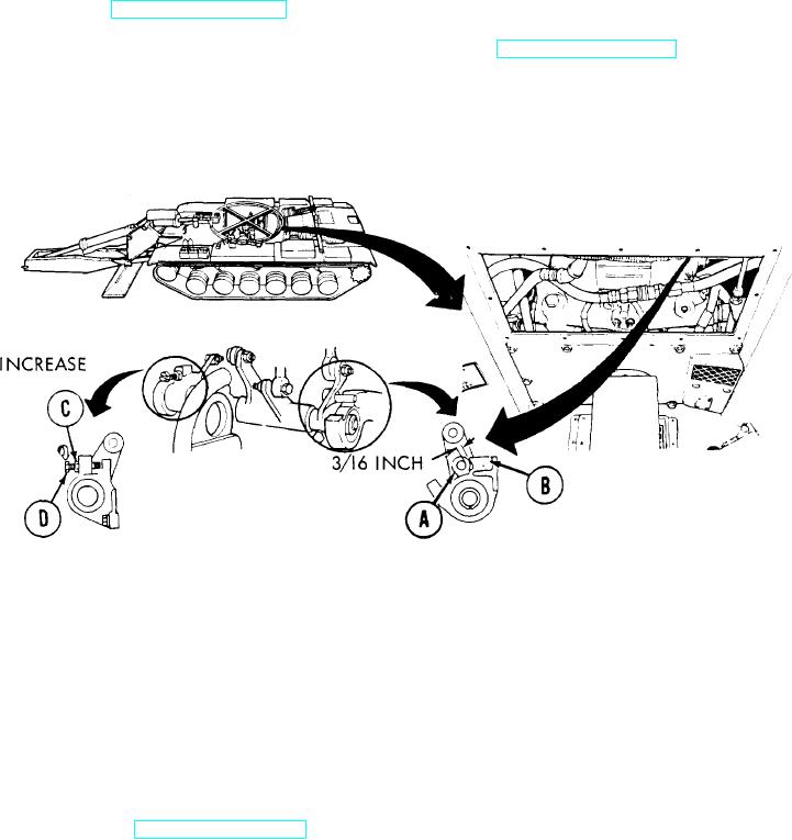
ADJUSTMENT:
1.
Using 3/16 inch end of fabricated gage, measure distance between stop pin (A) and bracket
shoulder (B).
2.
Using 3/16 inch end of fabricated gage, measure distance between stop pin (A) and bracket
shoulder (B).
If distance is more than or less than 3/16 inch, use wrench and loosen jamnut (C) on idle
3.
adjustment screw (D).
Using screwdriver, turn screw (D) to the right to increase distance, and to the left to
4.
decrease distance.
Using wrench, tighten jamnut (C).
5.
Check idle speed. If it is not between 700-750 rpm (shown on tachometer), notify support
6.
maintenance.
Stop engine (TM 5-5420-226-10).
7.
Install upper engine access cover (page 17-15).
8.
End of Task
TA107941