
TM 5-5420-226-20-2
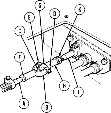
ACCELERATOR LINKAGE ADJUSTMENT (Sheet 2 of 6)
ADJUSTMENT:
Check to see that threaded shaft (A) is flush with
1.
inside of clevis (B) at location (C). If threaded
shaft is flush, go to step 5. If threaded shaft is
not flush, go to steps 2, 3, and 4.
Using pliers, remove cotter pin (D) and pin (E).
2.
Throw cotter pin away.
Using 9/16 inch wrench to hold clevis (B), use
3.
1/2 inch wrench to loosen nut (F) and adjust
clevis (B) so that shaft is flush with clevis.
Using 9/16 inch wrench to hold clevis (B), use
4.
1/2 inch wrench to tighten nut (F).
Insert 1/16 inch diameter pin at location (G)
5.
in rod end bearing (H) to be sure that threads
of tube assembly (J) go into rod end bearing
beyond location (G). If tube assembly is not
inserted beyond locatin (G), go to steps 6 and
7. If tube assembly is inserted beyond location
(G), go to step 8.
Using 7/16 inch wrench to hold rod end bearing (H)
6.
(on flats) and 1/2 inch wrench to loosen nut (K),
adjust rod end bearing as stated in step 5.
Using 7/16 inch wrench to hold rod end bearing (H)
7.
(on flats), use 1/2 inch wrench to tighten nut (K).
NOTE
Rod (H) or clevis (B) may be
pulled in order to insert pin (E).
8.
Insert pin (E) and, using pliers, install new cotter
pin (D).
TA108045
Go on to Sheet 3
7-339