
TM 5-5420-226-20-3
SHIFT LINKAGE ADJUSTMENT (Sheet 25 of 28)
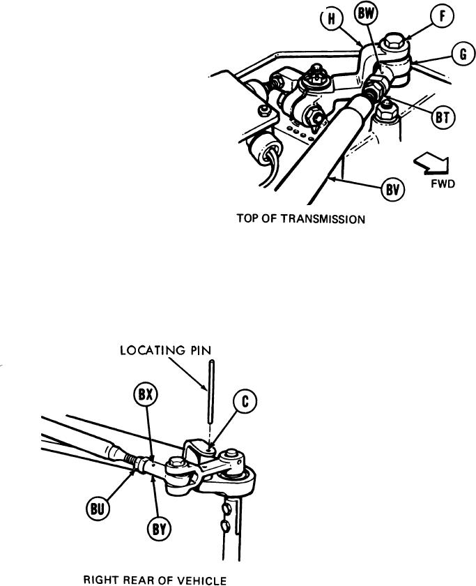
131.
Using small diameter wire, check to see if
shifting rod (BV) is past holes (BW) and
(B X). If shifting rod (BV) is past holes
(BW) and (BX), do steps 132 thru 135. If
shifting rod (BV) is not past hole (BW),
do steps 136 thru 145. If shifting rod (BV)
is not past hole (BX), go on to step 146.
132.
Using 9/16 inch wrench, install screw (F)
through clevis (H) and shifting rod bearing
end (G).
133.
Holding rod bearing ends (G) and (BY) with
9/16 inch wrench, use torque wrench and
9/16 inch crow foot adapter to tighten jamnuts
(BT) and (BU) to 16-18 lb-ft (22-24 Nm).
134.
Remove locating pin from alinement hole (C).
135.
Using torque wrench and 9/16 inch socket, tighten screw (F) to 16-18 lb-ft (22-24 Nm)
and go to step 156.
Go on to Sheet 26
TA169078
11-77