TM-5-5420-279-10
3.10.1.14 On the chest pack, move the joystick forward and rearward as necessary to align the
holes for the launch beam final stop locking pin.
WARNING
CRUSH HAZARD. FAILURE TO INSTALL THE LOCKING PINS AND THEIR R CLIPS WILL
CAUSE THE LAUNCH BEAM TO FLEX AND CREEP BACKWARDS. FAILURE TO HEED THIS
INSTRUCTION COULD RESULT IN SEVERE PERSONAL INJURY.
3.10.1.15 Install the locking pin and R clip to secure the launch beam final stop.
3.10.2.1
Operate the lift and traverse controls on the crane and position the crane to lift the end
beam.
3.10.2.2
Connect the two slings and tag lines to the end beam (Para 3.9.2).
3.10.2.3
Operate the lift and traverse controls on the crane, and lift the end beam into position on
the end beam adapters positioned on the launch vehicle slide frame.
3.10.2.4
Disconnect the two slings and tag lines from the end beam.
3.10.2.5
Connect the bridge module lifting beam and single leg sling to the crane.
3.10.2.6
Operate the lift and traverse controls on the crane and position the crane to lift the ramp
module.
3.10.2.7
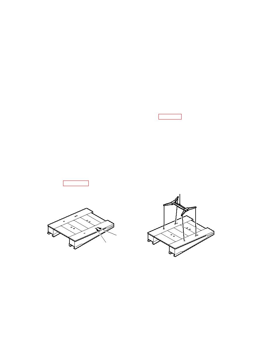
Connect the bridge module lifting beam at POSITION 2 and tag lines to the ramp module
(see Figure 3. 41).
FRONT
POSITION 1
REAR
POSITION 2
686A593
3.10.2.8
Operate the lift controls on the crane, and lift the ramp module. Make sure the module
opens slowly and progressively as it is lifted by the crane. Do not operate the traverse
controls of the crane until the ramp module has fully opened.
3.10.2.9
Operate the lift and traverse controls on the crane and, using the tag lines, guide the ramp
module into position over the end beam.


