TM-5-5420-279-10
3.10.4.6
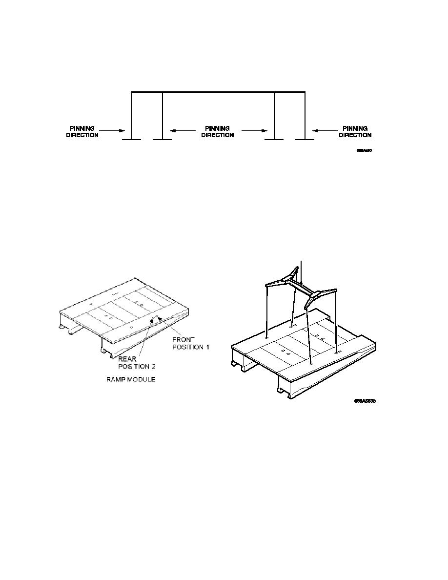
Lower the module to allow the sling to go slack and the pinning holes to align, pin the
modules together (the outside pins are fitted from the outside in and the two inside pins
are fitted from the inside out, so that the R clips are fitted inside the bridge) and clip.
Figure 3. 47 Method of Pinning Bridging Modules Together
3.10.5.1
Make sure the bridge module lifting beam is adjusted to its widest setting and secured in
this position with the shootbolts.
3.10.5.2
Attach the bridge module lifting beam to the crane hook.
3.10.5.3
Operate the lift and traverse controls on the crane and position the bridge module lifting
beam at the ramp module.
Figure 3. 48 Bridge Lifting Beam connected to POSITION 2
3.10.5.4
Connect the bridge module lifting beam to POSITION 2 lifting points on the outboard sides
of the ramp module. Attach steadying rope lines to the ramp module.
3.10.5.5
Remove the connecting pins securing the ramp module to its end beam, by twisting the
pins so that they disengage with the locking bracket.


