TM-5-5420-279-10
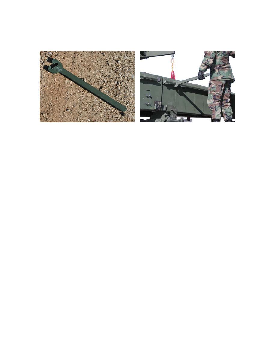
3.10.2.10 If necessary connect the ramp module wrench to the approach ramp gutter on the end
beam and rock the end beam to align the tapered guide.
Figure 3. 42 End Beam Wrench and Method of Use
3.10.2.11 Recover the end beam locking pins from the LVT basket and place them safely on the
slide frame platform.
3.10.2.12 Align the ramp module with the tapered guide on the end beam and slowly lower the ramp
module until the two are fully engaged and the ramp module is sat on the removable
rollers.
3.10.2.13 Insert the lower locking pins and secure them by twisting the pin so that they locate within
the locking bracket.
3.10.2.14 Disconnect the bridge module lifting beam and steadying rope lines from the lifting points
on the ramp module.
NOTE
It should be noted that the parallel modules are interchangeable and reversible when
connecting to each other and ramp modules.
3.10.3.1
In order to connect the bridging modules together to form a stable and secure structural
unit it is necessary to carry out the following procedure:
3.10.3.2
Once the bridge module is slung, it has to be aligned with the module fitted in place on the
sliding frame.
3.10.3.3
To connect the ramp module with the bridging module, the bridge module is slung into
position so that the top dowels on the two modules are aligned.
3.10.3.4
Sling the bridge module so that the dowels are inserted into their receptacles on the
connecting modules.
3.10.3.5
Insert all four shootbolts.


