TM-5-5420-279-10
4.18.1.1
Recover the tail lift pendant from its storage position, and connect the tail lift umbilical
cable to the tail lift vehicle connection point.
4.18.1.2
In the launch vehicle cab, to the right of the driving position, on the left side of the
center console, set the 4-position mode selector rotary switch from 1 to 2.
4.18.1.3
Retract shootbolts holding far bank support bearing pads and slowly lower the tail lift
until both pads can be removed from the tail lift.
4.18.1.4
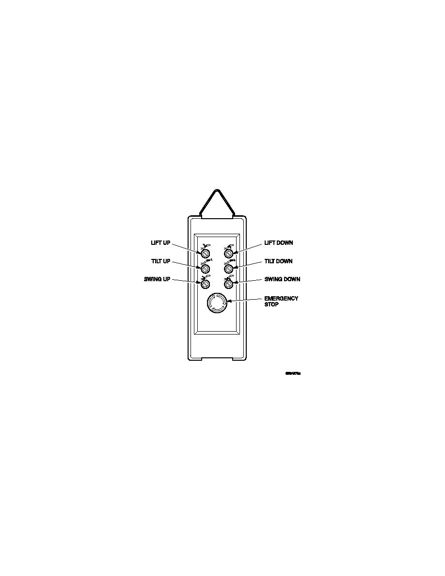
On the tail lift pendant operate the LIFT DOWN switch to lower the tail lift platform so
that it is just off the ground.
Tail lift Hand Control
4.18.1.5
Disengage the shootbolts securing the A-frame in the vertical position.
NOTE
If the locking pins are difficult to disengage, press and hold momentarily, the DEPLOY
pushbutton on the A-frame rotate, in the interface cabinet.
4.18.1.6
Make sure personnel are clear from the area around the A-frame.


