TM-5-5420-279-10
5.4.7.19
Operate the lift and traverse controls on the crane, to lift the upper section of the
approach ramp frame together with its five approach ramps.
5.4.7.20
Guide the approach ramp upper frame onto the lower frame ensuring that the
stacking lugs engage.
5.4.7.21
Connect the lifting hooks on the lower section of the approach ramp frames to the
oval rings on the upper approach ramp frame.
5.4.7.22
Position tag lines onto the upper section of the approach ramp frame.
5.4.7.23
Operate the lift and traverse controls on the crane and recover the complete frame
with its 10 approach ramps and stack them on the home bank approach ramps on
flatrack T1, ensuring that the transportation lugs engage with the sockets.
5.4.7.24
Disconnect the bridge module lifter and the tag lines from the approach ramp
frames.
5.4.7.25
Operate the lift and traverse controls on the crane and position the bridge module
lifter at the far bank ramp module.
5.4.7.26
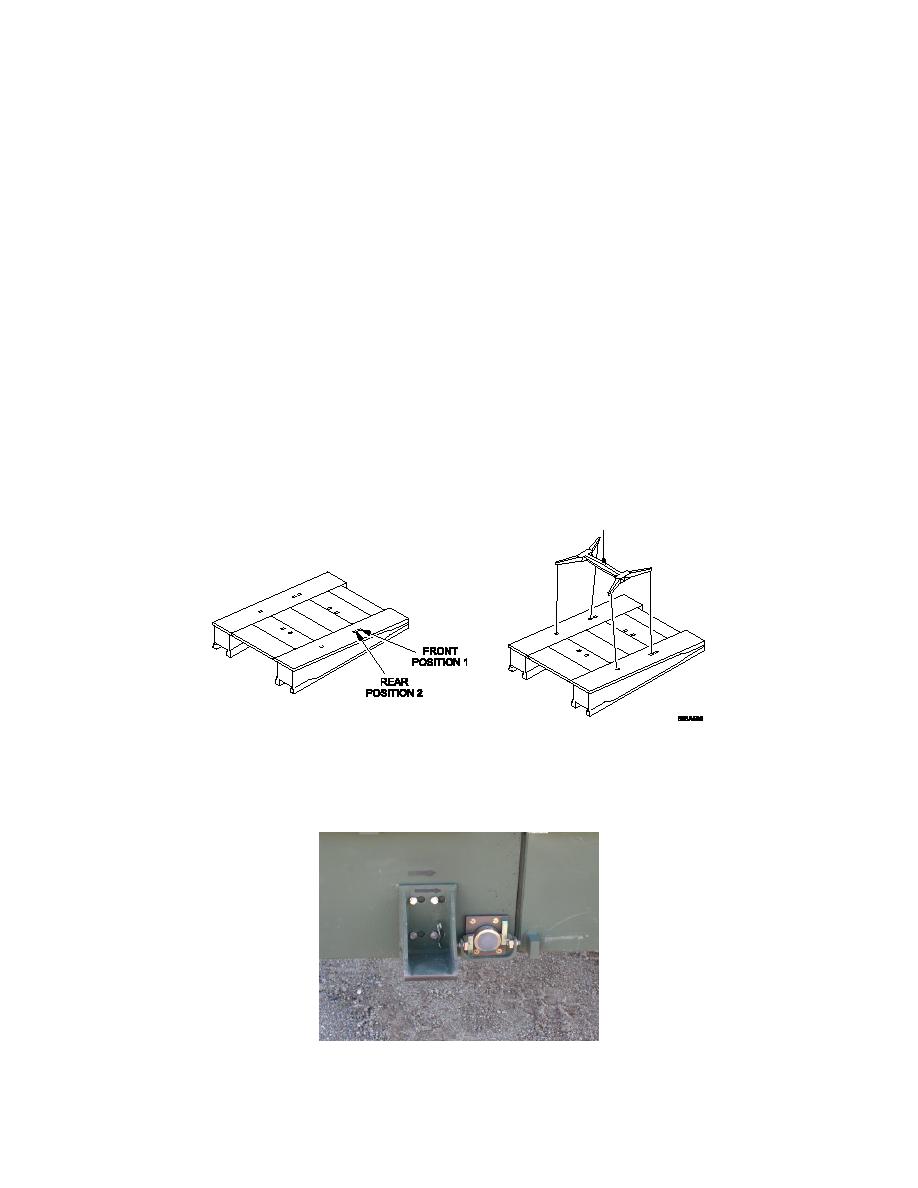
Connect the bridge module lifter to the rear lifting points (POSITION 2) on the
outboard sides of the far bank ramp module.
Bridge Module Lifter in POSITION 2
5.4.7.27
Remove the end beam pins securing the far bank ramp module to its end beam and
remove the ramp lead in bracket.
Ramp Module Lead in Bracket
5-32


