TM-5-5420-279-10
5.4.7.28
Position personnel to the side of the launcher to ensure the single leg sling remains
vertical during ramp module lifting.
5.4.7.29
Connect tag lines to the end beam pinning hole once the ramp module is raised
above the end beam.
5.4.7.30
Operate the lift controls on the crane and slowly raise the far bank ramp module
clear of the end beam.
NOTE
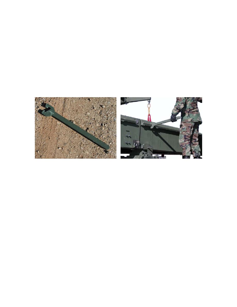
To assist in the separation of the ramp module and the end beam use the end beam
wrenches to apply back and forwards rocking movement to the end beam as the crane lifts
the ramp module.
End Beam Wrench and Operation
5.4.7.31
Use the traverse controls on the crane and rotate the far bank ramp so that it is 90
across flatrack V1 and resting on the 5th parallel module stacked on flatrack V1.
WARNING
CRUSH HAZARD. DEATH OR PERSONAL INJURY CAN RESULT IF THE CORRECT
PROCEDURE IS NOT FOLLOWED FOR ATTACHMENT OF THE BRIDGE MODULE LIFTER
TO THE PARALLEL MODULE.
5.4.7.32
Disconnect and adjust the bridge module lifter to its middle setting and secure it in
position with shootbolts.
5.4.7.33
Connect the bridge module lifter to the wire ropes located between the deck units of
the far bank ramp module.
5.4.7.34
Remove any debris or stones from the hinge lines of the far bank ramp module.
5.4.7.35
Operate the lift and traverse controls on the crane and, using the tag lines, guide the
far bank ramp module into position on top of the parallel module on flatrack V1 with
the jaws located at the front of the flatrack.
5-33


