
TM
5-5420-202-20-2
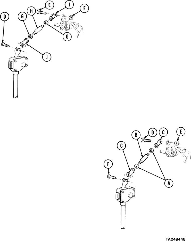
ACCELERATOR LINKAGE ENGINE CONTROL REPLACEMENT (Sheet 2 of 2)
REMOVAL:
1.
Using 7/16 inch wrench, remove screw
2.
Using two 7/16 inch wrenches, remove
(E) and Nut (F).
3.
Using 1/2 inch wrench and 7/16 inch wrench,
loosen nuts (G) from stud (H).
Count and write down number of turns needed to
unscrew rod ends (J).
NOTE
Count and write down number of turns needed to unscrew
rod ends (J).
Unscrew rod ends (J) and nuts (G) from stud (H).
4.
C L E A N I N G AND INSPECTION:
1.
Clean all parts using dry cleaning solvent and clean rags.
2.
Inspect all parts for bends, cracks, stripped threads, wear, or other defects. Replace
d e f e c t i v e parts.
INSTALLATION:
1.
Install nuts (A) onto stud (B).
2.
Screw rod ends (C) to same number of
turns recorded for removal on stud (B).
Using 1/2 inch wrench and 7/16 inch
3.
wrench, tighten nuts (A).
4.
Position rod assembly in place.
5.
Using two 7/16 inch wrenches, install
screw (D) and nut (E).
6.
Using 7/16 inch wrench, install screw (F).
7.
Install engine upper access cover (page 17-12)
End of Task