
TM 5-5420-202-20-2
COOLING FAN SHROUD Replacement (Sheet 3 of 8)
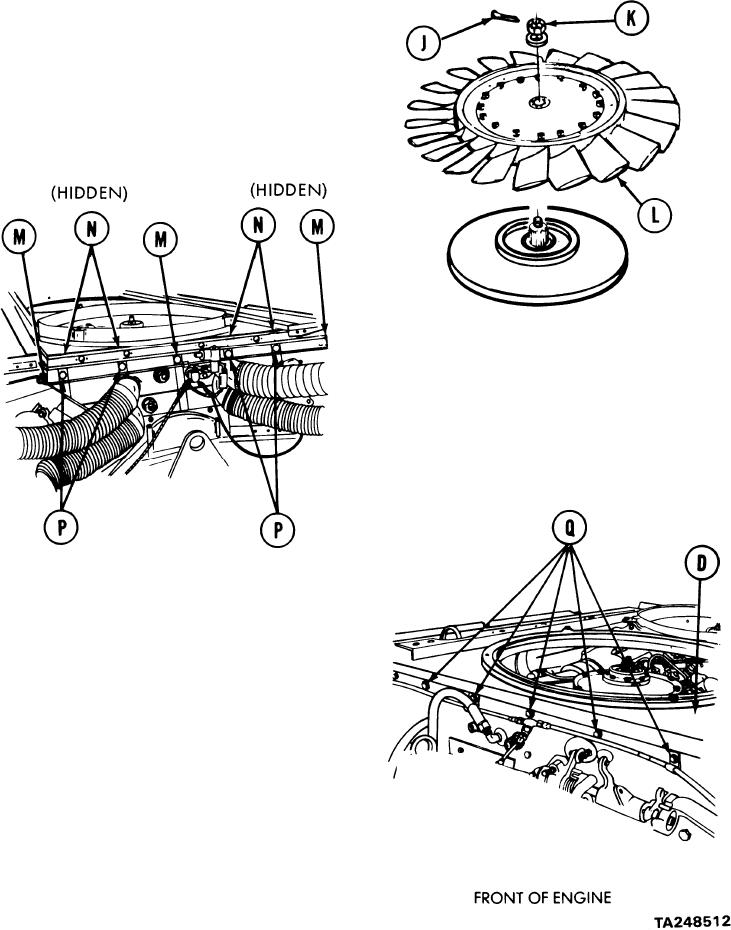
Using pliers, remove cotter pins (J)
8.
from nuts (K) from each fan (L).
Using 1-1/4 inch socket, remove nut
9.
and washer (K) securing each fan (L)
to engine.
10.
Lift fans (L) from engine.
NOTE
Four nuts (N) are located under fan
shroud and hold fuel line clamps. When
nut (N) and screws (P) are removed,
clamps will remain on fuel line.
Using 1/2 inch socket, remove three
11.
screws (M).
Using 1/2 inch wrench to hold nuts (N),
12.
use 1/2 inch socket and remove four
screws (P) and nuts (N).
Using 1/2 inch socket, remove five screws
13.
(Q) securing shroud (D) to engine.
Go on to Sheet 4
9-49