
TM 5-5420-202-20-2
COOLING FAN SHROUD REPLACEMENT (Sheet 6 of 8)
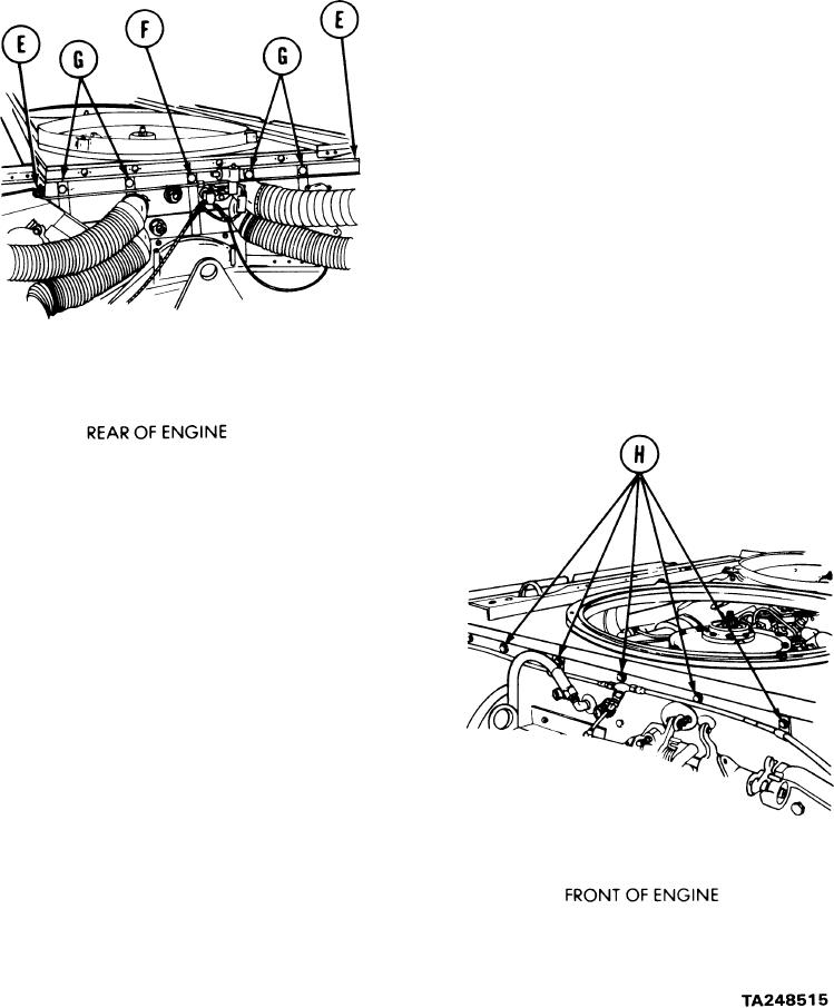
5.
Using 1/2 inch socket, install two screws
(E) securing shroud and fuel line clamps
to engine.
6.
Using 1/2 inch socket, install one screw
(F) securing shroud to engine.
7.
Using 1/2 inch socket, install four screws
(G) securing shroud to engine.
8.
Position clamps on fuel line, located
on underside of shroud, onto screws
(G). Using 1/2 inch wrench, install four
nuts onto screws (G) securing fuel line
clamp.
Using 1/2 inch socket, install five screws
9.
(H) securing clamps and engine shrouds
to fan shrouds.
Go on to Sheet 7
9-52