
TM 5-5420-202-20-2
TURBOCHARGER SHROUDS REPLACEMENT (Sheet 5 of 5)
Upper Shroud Replacement (Sheet 1 of 1)
TOOLS:
1/2 in. combination box and open end wrench
1/2 in. socket with 1/2 in. drive
5 in. extension with 1/2 in. drive
Ratchet with 1/2 in. drive
P R E L I M I N A R Y PROCEDURES:
Remove powerplant (page 5-2).
Remove rear engine shroud support (page 9-39).
NOTE
Procedures for replacement of the left or right
transmission shrouds are similar. Procedures
for the left side are shown.
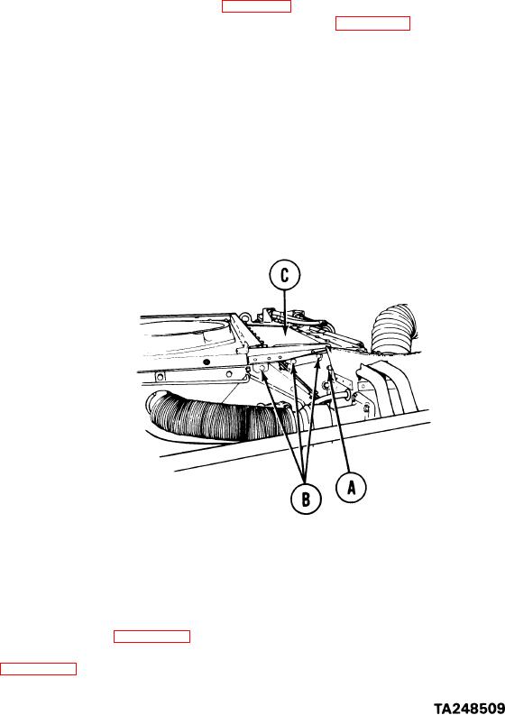
REMOVAL:
1.
Using 1/2 inch socket with extension and 1/2 inch wrench, remove screw, lockwasher,
and nut (A).
2*
Using 1/2 inch socket with extension, remove three screws and lockwashers (B).
3.
Remove upper shroud (C).
INSTALLATION:
1.
Position upper shroud (C) in place.
2.
Install three screws and washers (B).
3.
Install screw, lockwasher, and nut (A).
4.
Using 1/2 inch socket with extension and 1/2 inch wrench, tighten screws (A and B).
5.
Install rear engine shroud support (page 9-40).
6.
Install powerplant (page 5-14).
End of Task