
TM 5-5420-202-20-2
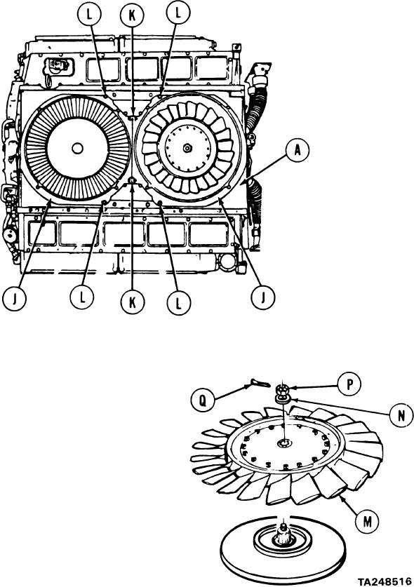
COOLING FAN SHROUD REPLACEMENT (Sheet 7 of 8)
Position two pieces of fan housing (J) onto powerplant.
10.
Using two 9/16 inch wrenches, install two screws, washers, and nuts (K) securing two
11.
pieces of fan housing (J) together.
Using 9/16 inch socket, install four screws and washers (L) securing fan housing (J) to
12.
fan shroud (A).
Using hands, position two fans (M) onto engine.
13.
Using 1-1/4 inch socket, install on each fan
14.
washer (N) and nut (P) securing fans (M) to
engine.
Using 1-1/4 inch socket and torque wrench,
15.
tighten nuts (P) to 50-55 lb-ft (68-75 NZm).
Back nuts (P) off until slot in nut (P) alines
16.
with hole in shaft. Using pliers, install
cotter pins (Q).
Go on to Sheet 8
9-53