
TM 5-5420-202-20-2
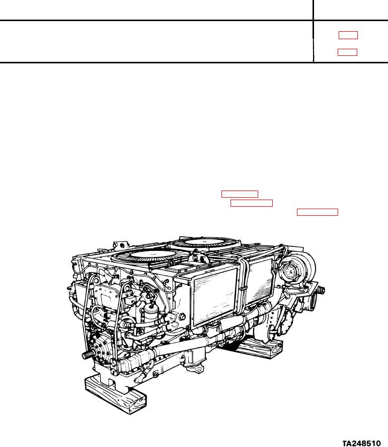
COOLING FAN SHROUD REPLACEMENT (Sheet 1 of 8)
PROCEDURE INDEX
PROCEDURE
PAGE
Removal
Installation
9/16 in. combination box and open end wrench (2 required)
TOOLS:
Slip joint pliers
9/16 in. socket with 1/2 in. drive
1/2 in. socket with 1/2 in. drive
3 in. extension with 1/2 in. drive
R a t c h e t with 1/2 in. drive
Thickness gage (feeler gage)
1 - 1 / 4 in. socket with 1/2 in. drive
1/2 in. combination box and open end wrench
T o r q u e wrench with 1/2 in. drive (0-175 lb-ft) (0-237 NZm)
Cotter pin
SUPPLIES:
Remove powerplant (page 5-2).
P R E L I M I N A R Y PROCEDURES:
Remove engine shroud (page 9-30).
Remove front and rear shroud supports (page 9-39).
Go on to Sheet 2