
TM 5-5420-202-20-3
SHIFT LINKAGE ADJUSTMENT (Sheet 7 of 28)
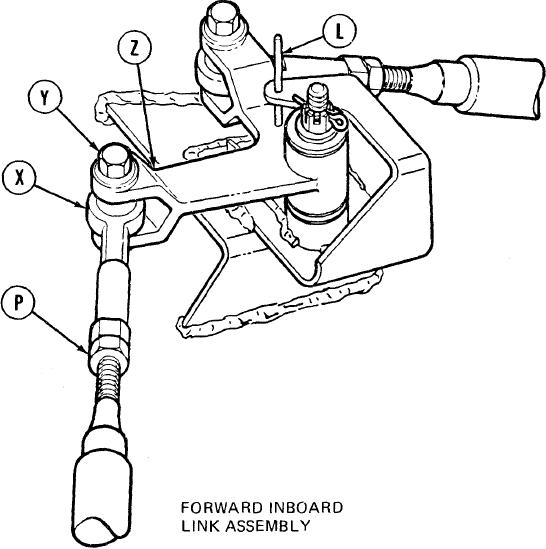
24.
Using 9/16 inch wrench, adjust shifting rod
bearing end (X) by turning clockwise or counter-
clockwise until screw (Y) will drop freely
through clevis (Z) and shifting rod bearing
end (X).
25.
Using 9/16 inch wrench, install screw (Y)
through clevis (Z) and shifting rod bearing
end (X).
26.
Holding rod bearing end (X) with 9/16 inch wrench, use torque wrench and 9/16 inch
crowfoot adapter to tighten jamnut (P) to 16-18 lb-ft (22-24 Nm).
27.
Remove locating pin (L) from alinement holes.
28.
Using torque wrench and 9/16 inch socket, tighten screw (Y) to 16-18 lb-ft (22-24 Nm)
and go to step 39.
Go on to Sheet 8
TA249324
11-58