
TM 5-5420-202-20-3
SHIFT LINKAGE ADJUSTMENT (Sheet 4 of 28)
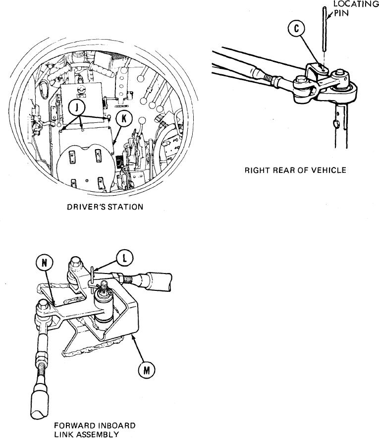
6.
Go to right rear of vehicle and try to insert
locating pin into alinement hole (C). If
locating pin cannot be inserted, go to step 7.
If locating pin can be inserted, go to step 127.
At driver's station, using 9/16 inch wrench,
7.
remove six bolts (J) securing access plate and
gasket (K) to floor in front of driver's seat.
8.
Remove access plate and gasket (K).
At forward inboard link assembly, try to
9.
insert locating pin (L) into alinement holes
in bracket (M) and link (N). If locating
pin (L) can be inserted, remove locating
pin (L) and go to step 39. If locating pin (L)
cannot be inserted, go on to step 10.
TA249321
Go on to Sheet 5
11-55