
TM 5-5420-202-20-3
SHIFT LINKAGE ADJUSTMENT (Sheet 10 of 28)
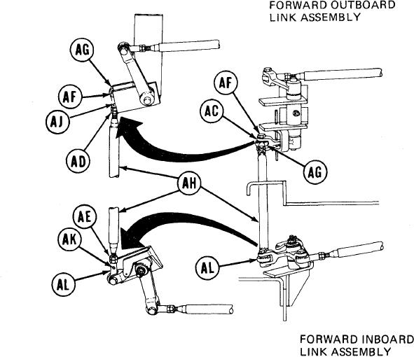
44.
Using 9/16 inch wrench, adjust shifting rod
bearing end (AG) by turning clockwise or
counterclockwise until screw (AF) will drop
freely through clevis (AC) and shifting rod
bearing end (AG).
45.
Using small diameter wire, check to see if
shifting rod (AH) is past holes (AJ) and
(AK). If shifting rod (AH) is past holes
(AJ) and (AK), do steps 46 thru 48. If
shifting rod (AH) is not past hole (AJ),
do steps 49 thru 57. If shifting rod (AH)
is not past hole (AK), go on to step 58.
46.
Using 9/16 inch wrench, install screw (AF)
through clevis (AC) and shifting rod bearing
end (AG).
47.
Holding rod bearing ends (AG) and (AL) with 9/16 inch wrench, use torque wrench and
9/16 inch crow foot adapter to tighten jamnuts (AD) and (AE) to 16-18 lb-ft (22-24 Nm).
48.
Using torque wrench and 9/16 inch socket, tighten screw (AF) to 16-18 lb-ft (22-24 Nm)
and go on to step 68.
Go on to Sheet 11
TA249327
11-61