
TM 5-5420-202-20-3
SHIFT LINKAGE ADJUSTMENT (Sheet 14 of 28)
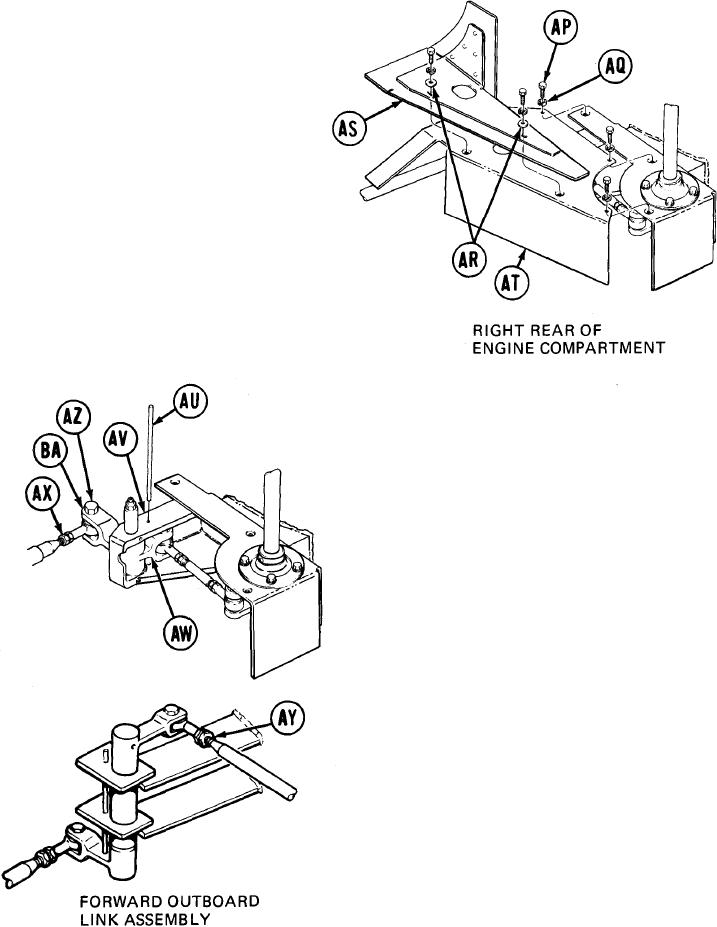
Using 7/16 inch socket, remove five screws
70.
(AP), lockwashers (AQ), and two flat
washers (AR).
71.
Using hands remove seal assembly (AS) and
shield (AT).
72.
Try to insert locating pin (AU) into alinement
holes in bracket (AV) and link (AW). If
locating pin (AU) can be inserted, go to step
103. If locating pin cannot be inserted, go on
to step 73.
Using 9/16 inch wrench, loosen jamnuts (AX)
73.
and (AY).
74.
Using 9/16 inch wrench, remove screw (AZ).
75.
Using hands move clevis (BA) and insert
locating pin (AU) into alinement holes in
bracket (AV) and link (AW).
TA249331
Go on to Sheet 15
11-65