
TM 5-5420-202-20-3
SHIFT LINKAGE ADJUSTMENT (Sheet 18 of 28)
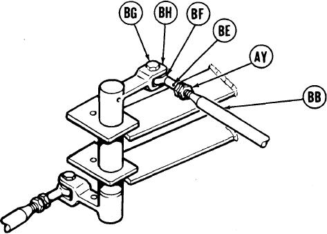
FORWARD OUTBOARD
LINK ASSEMBLY
92.
Using 9/16 inch wrench, remove screw (BG).
NOTE
Do not allow shifting rod (BB) to turn while doing
step 93. Shifting rod (BB) is made up of more than
one piece and may come apart if allowed to turn.
93.
Using 9/16 inch wrench, adjust shifting rod bearing end (BF) by turning clockwise
until shifting rod (BB) is past hole (BE).
94.
Using 9/16 inch wrench, install screw (BG) through clevis (BH) and shifting rod bearing
end (BF).
95.
Holding rod bearing end (BF) with 9/16 inch wrench use torque wrench and 9/16 inch
crow foot adapter to tighten jamnut (AY) to 16-18 lb-in (Nm).
96.
TA249335
Go on to Sheet 19
11-69