
TM 5-5420-202-20-3
SHIFT LINKAGE ADJUSTMENT (Sheet 16 of 28)
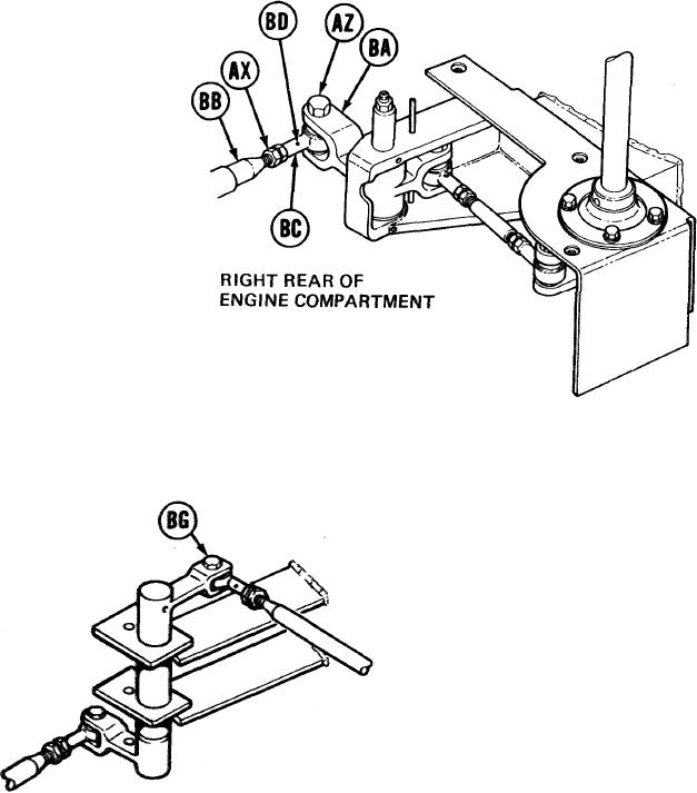
81.
Using 9/16 inch wrench, remove screw (AZ).
82.
Using 9/16 inch wrench, adjust shifting rod
bearing end (BC) by turning clockwise until
shifting rod (BB) is past hole (BD).
83.
Using 9/16 inch wrench, remove screw (BG).
84.
Using 9/16 inch wrench, install screw (AZ)
through clevis (BA) and shifting rod bearing
end (BC).
FORWARD OUTBOARD
LINK ASEMBLY
85.
Holding rod bearing end (BC) with 9/16 inch wrench, use torque wrench and 9/16 inch
crowfoot adapter to tighten jamnut (AX) to 16-18 lb-ft (22-24 Nm).
Using torque wrench and 9/16 inch socket, tighten screw (AZ) to 16-18 lb-ft (22-24 Nm).
86.
Go on to Sheet 17
TA249333
11-67