
TM 5-5420-202-20-3
HUB ASSEMBLY REPLACEMENT (Sheet 6 of 7)
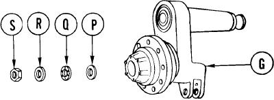
14. When nut (P) is tight and parts seem to be seated, back off nut and, using torque wrench, tighten
nut (P) to 50-70 lb-ft (68-95 N.m).
15. Back off round nut (P) 1/4 turn.
16. Install lock (Q) so that hole of lock fits over nut (P) dowel.
NOTE
I f loc k hole doe s not line up t o dow e l of nut , t urn loc k ove r
a nd t ry ot he r side .
17. Position new bearing nut lock (R) to one of holes in lock (Q).
18. Screw nut (S) onto arm (G) lower spindle. Tighten nut up against bearing nut lock (R).
19. Using 2-1/2 inch socket, tighten nut (S).
20. Using hammer and drift punch, bend one end of bearing nut lock (R) back over nut (S).
TA249547
Go on to Sheet 7