
TM 5-5420-202-20-3
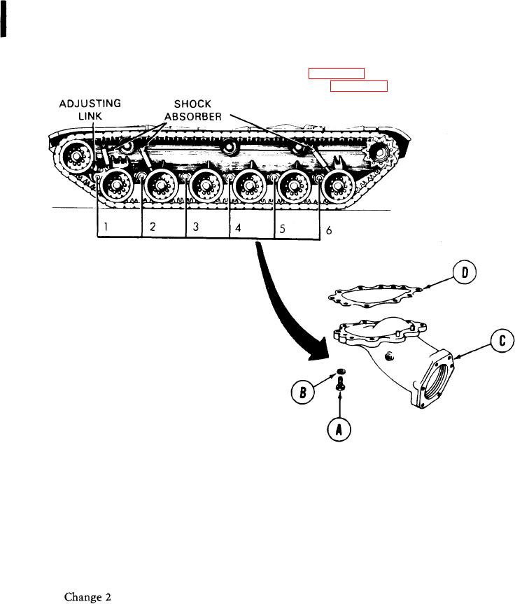
ROADWHEEL SUPPORT HOUSING ASSEMBLY REPAIR AND REPLACEMENT (Sheet 1 of 2)
10 in. adjustable wrench
TOOLS: 1-5/16 in. socket with 3/4 in. drive
Slip joint pliers
Ratchet with 3/4 in. drive
Torque wrench with 3/4 in. drive (0-600 lb-ft)
Hammer
36 in. extension bar
(0-814 N.m)
Drift pin punch
Lockwashers (9 required)
SUPPLIES:
Corrosion preventive (Item 79, Appendix D)
Solid film lubricant (Item 80, Appendix D)
PERSONNEL: Two
PRELIMINARY PROCEDURES:
Remove roadwheel arm (page 14-2)
Remove torsion bar anchor (page 14-31)
NOTE
There are six support housings on
side
of
each
vehicle.
The
procedures for all six are identical
e x c e p t that no. 1 housing is not
interchangeable.
NOTE
Use jack to support housing
during removal and installation.
REMOVAL:
1.
Using socket with ratchet, remove nine
screws (A) and lockwashers (B) securing
roadwheel support housing (C) to hull.
2.
Remove housing (C) and gasket (D) from hull
mounting place. Throw gasket (D) away.
Go on to Sheet 2