TM 5-5420-202-34
ACCELERATOR CONTROL LINKAGE ASSEMBLY REPLACEMENT (Sheet 5 of 6)
6.
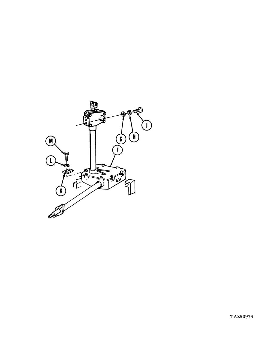
Aline two holes in base of accelerator control linkage assembly (F) with two lower mounting
holes on floor of engine compartment.
NOTE
Make sure that tab on side of
housing slides between two guides
welded to floor of hull.
7.
Aline two holes on upper end of accelerator
control linkage assembly (F) with two holes
in bracket attached to bulkhead.
8.
Using 9/16 inch socket, install two flat
washers (G), lockwashers (H), and screws
(J).
Aline holes in plate (K) with holes in base
9.
of accelerator control linkage assembly (F).
10.
Using 9/16 inch socket, install two lock-
washers (L) and screws (M) through plate
(K) and accelerator control linkage assembly
(F).
Go on to Sheet 6
4-97


