
TM 5-5420-226-20-2
FUEL-WATER SEPARATOR FLUID PRESSURE FILTER ASSEMBLY REPLACEMENT (Sheet 7 of 7)
Using rags, wipe bottom of fuel-water separator
13.
filter and connecting lines clean of fuel.
14.
Remove drip pan.
TEST:
1.
Per form operational check of automatic drain (page 7-233).
2.
Connect engine for powerplant ground hop (pag
3.
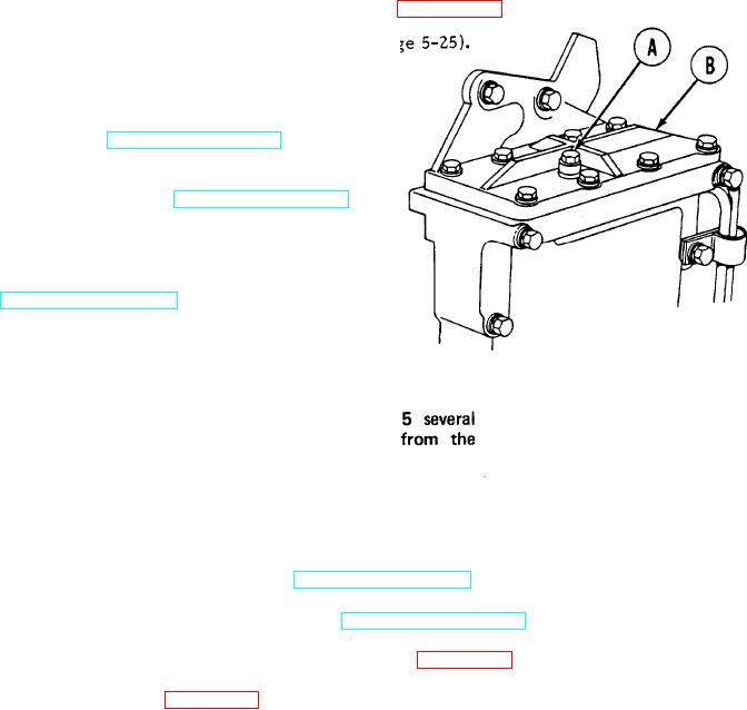
Using 7/1 6 inch wrench, open bleed cap (A).
4.
Set FUEL PUMPS switch on master control
panel to ON (TM 5-5420-226-10).
5.
Set MASTER BATTERY switch on master
control panel to ON (TM 5-5420-226-10).
Watch bleed cap (A) of fuel-water separator
filter (B) for air release (bubbles).
6.
Set MASTER BATTERY switch to OFF
(TM 5-5420-226-10). After about 1
minute, repeat step 4. When constant
fuel flow is seen, go to step 7.
NOTE
It may be necessary to perform steps 4 and
times until a constant fuel flow (no bubbles)
bleed cap (A) is observed.
7.
Check for leaks and tighten or replace components as necessary.
8.
Using 7/16 inch wrench, turn fuel-water separator bleed cap (A) to the right until snug.
Set FUEL PUMPS switch to OFF (TM 5-5420-226-10).
9.
10.
Set MASTER BATTERY switch to OFF (TM 5-5420-226-10).
11.
Disconnect engine from powerplant ground hop (page 5-40).
12.
Install powerplant (page 5-14).
TA107822
End of Task