
TM 5-5420-226-20-2
ACCELERATOR LINKAGE ADJUSTMENT (Sheet 4 of 6)
17.
Have one person in driver's station
ready to start engine and watch
tachometer while the other person
measures accelerator travel at engine.
18.
Start engine (TM 5-5420-226-10).
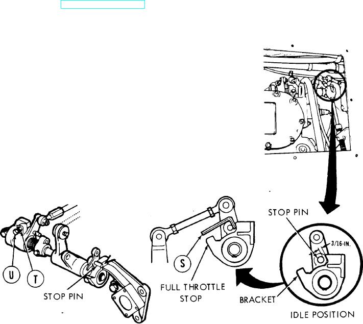
Using fabricated go/no-go gage (S), measure
19.
for at least 1/8 inch and not more than 3/16
inch clearance at idle speed (700-750 rpm).
If idle adjustment is necessary, perform steps
20 and 21. If adjustment is not necessary, go
on to step 22.
20.
Using 1/2 inch wrench, loosen nut (T).
Adjust idle adjustment screw (U) to the
requirements of step 19. If requirements
are met, go to step 22. If requirements
cannot be met, notify support maintenance.
21.
Using 1/2 inch wrench, hold idle adjust-
ment screw (U). Using 1/2 inch wrench,
tighten nut (T).
TA108047
Go on to Sheet 5