
TM 5-5420-226-20-2
ACCELERATOR LINKAGE ADJUSTMENT (Sheet 5 of 6)
22.
Stop engine (TM 5-5420-226-10).
23.
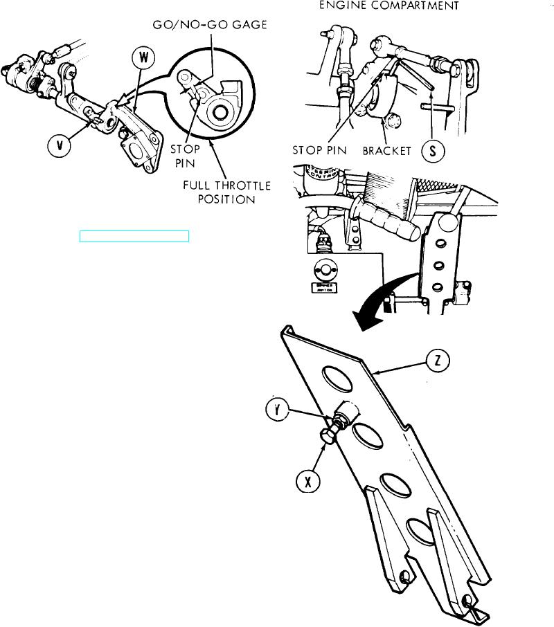
Insert either end of go/no-go gage (S) between
stop pin (V) and bracket (W). Hold in this
position while person in driver's station
presses pedal to full throttle position.
24.
With pedal in full throttle position, screw (X)
must contact floor and stop pin must contact
either end of go/no-go gage (S). If this require-
ment cannot be met, do steps 25 and 26. If
requirement is met, go to step 27.
25.
Using two 9/16 inch wrenches, loosen nut (Y)
and screw (X) on back side of accelerator
pedal (Z).
26.
Using two 9/16 inch wrenches, hold screw (X)
and tighten nut (Y).
27.
Holding pedal down (full throttle position), turn
screw out until it is against floor. It may be necessary
to press pedal down, raise and adjust, press it down
again, raise and adjust several times.
Go on to Sheet 6
TA108048
7-342