
TM 5-5420-226-20-3
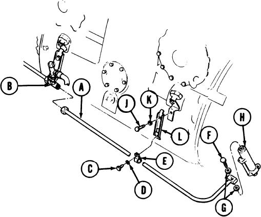
BRAKE RIGHT HAND SLAVE CYLINDER AND TUBE ASSEMBLY REPLACEMENT (Sheet 2 of 6)
1.
Position container under tube (A) and
tee (B) to catch brake fluid.
2.
Using 11/16 inch wrench, disconnect
nut of tube assembly (A) from tee (B).
NOTE
Allow brake fluid to drain. Dispose
of fluid in accordance with local pro-
cedures.
3.
Using 7/16 inch socket, remove screw
(C), lockwasher (D), and clamp (E).
4.
Using 13/1 6 inch box wrench, loosen
bolt (F) from slave cylinder.
5.
Remove bolt (F), tube (A), and two gaskets
(G) as an assembly from slave cylinder
(H). Throw away gaskets (G).
Install plastic cap on tee (B).
6.
Install plastic plug in nut of tube assembly
7.
(A) and masking tape on parts in other
end.
8.
Using 9/16 inch socket, remove screw
(J), lockwasher (K), and bracket (L).
NOTE
Replace screw (J) and Iockwasher (K) to hold adjusting screw lock plate in
place until installation of bracket (L).
Go on to Sheet 3
TA169184
13-59