ARMY TM 5-5420-212-10-1
MARINE CORPS TM 08676A-10/1-1
(2)
Remove retainer clips and washers from headless pin in nose link, then remove headless pin.
(3)
Disconnect 1N2 upper from 2N2 upper and remove 1N2 upper.
(4)
Disconnect 2N2 upper from 3N2 upper then remove both these nose sections.
(5)
Follow steps (6) to (9) in paragraph 4-13a.
4-14.
ASSEMBLING LAUNCHING NOSES FOR DELAUNCH
a.
Single Story 8 thru 12 Bay. Double Story 2E + 1 thru 2E + 22
When the launching nose is to be assembled ready for delaunch, the launching nose, launching nose cross girder and
posts will be fitted to the far bank end of bridge. In the procedure below, double story is illustrated, but the procedures are the
same for 8 thru 12 bay single story.
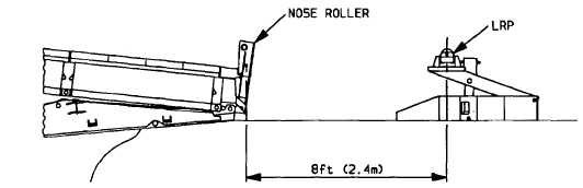
(1)
Place landing roller pedestal (LRP) 8 ft (2.4m) from bankseat beam. This distance is measured from nose roller
to center of landing roller.
(2)
Place partly raised [about 6 in (15 cm)] 15 ton jack in landing pedestal. Ensure jack is seated in base of landing
roller pedestal and hood of landing roller pedestal is on head of jack correctly.
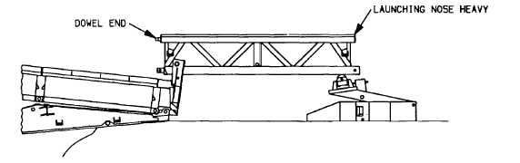
(3)
Place first heavy nose section on nose roller and landing roller pedestal. Dowel end of nose unit faces cross
girder. Place a panel pin through nose roller and nose section.
Support first nose section and add second heavy nose section.
(5)
Remove panel pin from nose roller and move nose toward launching nose cross girder until nose pin is within 1 ft
(0.3 m) of nose roller.
(6)
Place panel pin through nose roller and nose section.
4-47