ARMY TM 5-5420-212-10-1
MARINE CORPS TM 08676A-10/1-1
b.
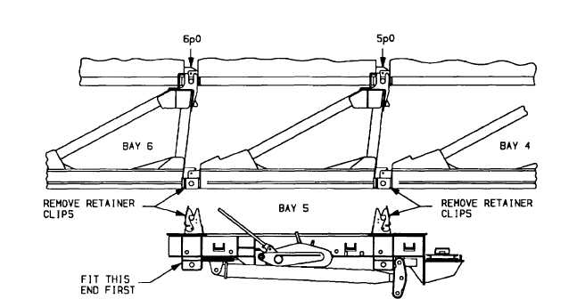
Fitting Post Tensioning Assembly, Footwalk and Second Link
Post tensioning assemblies can be right or left handed. Ensure that correct assembly is used. Pulley end of assembly
must be toward closest bankseat beam with cable puller rigged on outside of bridge. The drill for fitting the first post tensioning
assembly at bay 5 is described below.
(1)
Position post tensioning assembly under bay 5 which will be positioned in front of the capsill roller beam.
(2)
Remove retainer clips from upper jaws of post tensioning assembly, these clips will be put back in when jaws lock
around panel pins.
(3)
Remove retainer clips from panel pins at 5p0 and 6p0 (bottom panel pins). These clips will be put back in after
upper jaws are secured to panel pins.
NOTE
Ensure that bottom panel pins are fully seated. If not, shoulder of pin will Interfere with connection of
post tensioning assembly. These pins must have been checked when bay 5 and 6 were added and the
same procedure will be carried out five bays from the near end of bridge.
(4)
Lift post tensioning assembly until upper jaws engage and lock around ends of panel pins in bottom panel. To
ease operation, engage jaws one end at a time, fitting at 6p0 first and 5p0 second. Put retainer clip back in each
upper jaw and each bottom panel pin.
4-56