
TM 5-5420-202-20-2
THERMOSTATIC ENGINE OIL COOLER VALVE ASSEMBLY (LEFT AND RIGHT)
REPLACEMENT (Sheet 4 of 4)
INSTALLATION:
Compressed air used for cleaning purposes will not exceed 30 psi.
Use only with effective chip guarding and personal protective
equipment goggles/shield, gloves, etc.
NOTE
If replacing valve assembly, the engine oil cooler bypass valve also
has to be replaced. Go to page 6-55 for replacement.
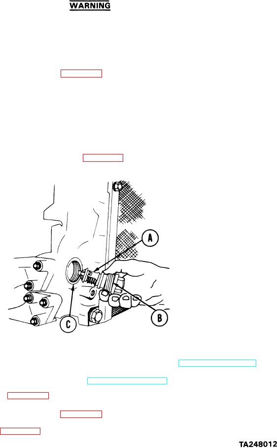
Using low-pressure compressed air, dry valve (A).
1.
Install new spacer ring (B) on valve (A).
2.
Seat threads of valve (A) in engine oil cooler socket (C) by hand.
3.
4.
Using wrench, tighten valve (A).
Replace left engine cooler (if required) (page 6-19).
5.
Replenish lubricating oil lost during valve assembly replacement (LO 5-5420-202-12).
6.
Check engine oil level indicator gage rod (TM 5-5420-202-10).
7.
Perform ground hop (page 5-25).
8.
Disconnect ground hop equipment (page 5-40).
9.
Install powerplant (page 5-14).
10.
End of Task