
TM 5-5420-202-20-2
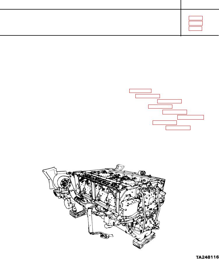
POWERPLANT LEFT BANK OIL COOLER FRAME AND BRACKETS REPLACEMENT (Sheet 1 of 9)
PROCEDURE INDEX
PROCEDURE
PAGE
Removal
Inspection
Installation
TOOLS: Ratchet with 1/2 in. drive
Alining punch
5 in. extension with 1/2 in. drive
1/2 in. combination box and open end wrench
1/2 in. socket with 1/2 in. drive
3/8 in. combination box and open end wrench
5/8 in. socket with 1/2 in. drive
9/16 in. combination box and open end wrench
9/16 in. socket with 1/2 in. drive
11/16 in. socket with 1/2 in. drive
4 in. flat-tip screwdriver
PERSONNEL:
Two
PRELIMINARY
PROCEDURES:
Remove
powerplant (page 5-2)
Remove
engine shroud (page 9-30)
Remove
centrifugal fan housing (page 9-64)
Remove
engine cooling fans (page 9-55)
Remove
engine cooling fan shroud (page 9-47)
Remove
engine access covers (left bank) (page 6-112)
Remove
engine left oil cooler (page 6-19)
Remove
transmission left oil cooler (page 6-38)
SUPPLIES:
Shims
S e l f - l o c k i n g nuts
Go onto Sheet 2