
TM 5-5420-226-20-2
FRONT POWERPLANT GUIDE (LEFT OR RIGHT) REPLACEMENT (Sheet 1 of 1)
TOOLS: 15/ 16 in. combination box and open end wrench
15/16 in. socket with 3/4 in. drive
Hinged handle with 3/4 in. drive
Torque wrench with 3/4 in. drive (0-600 ft-lb) (0-813 N. m)
PRELIMINARY PROCEDURE: Remove powerplant (page 5-2)
Torque wrench adapter (Item 34, Chapter 3, Section I)
SPECIAL TOOLS:
REMOVAL:
NOTE
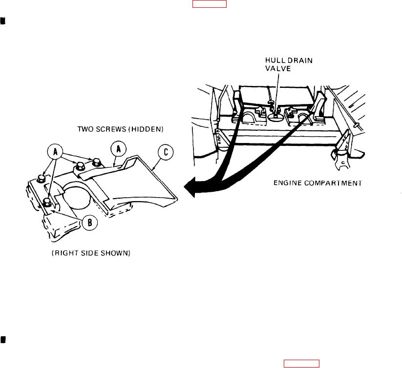
Three screws on right guide and two screws on left guide
are inaccessible and cannot be loosened or removed using
socket, Use wrench to remove screws that cannot be
removed using socket.
1. Using socket with hinged handle or wrench,
loosen and remove six screws and lock-
washers (A).
2.
Remove inner support (B)
and front guide (C).
INSTALLATION:
1.
Mount inner support (B) and
front guide (C).
2.
Install six screws and lockwashers
(A).
NOTE
Three screws on right guide and two screws on left guide
cannot be torqued. Use wrench to tighten screws that can-
not be torqued.
Using socket or torque wrench adapter, tighten
3.
screws (A) to 155-215 lb-ft (212-286 Nom).
Install powerplant (page 5-14)
4.
End of Task