TM 5-5420-202-34
SHIFTING CONTROL SLEEVE ASSEMBLY REPLACEMENT AND REPAIR (Sheet 4 of 4)
INSTALLATION:
1.
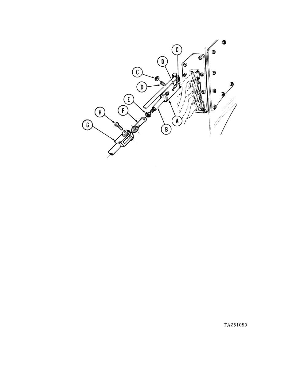
Slide sleeve assembly (A) over shaft assembly (B) as far as it will go.
Using 7/16 inch wrench to hold nut (C) and key to turn screws (D), install two sleeve
2.
holding screws (D) through lock nuts (C) into sleeve (A) until screws bottom out on hull
connector. Hold screw and, using torque wrench and 7/16 inch crow foot, tighten nut
(C) to 7.5 lb-ft (10 Nm).
3.
Using 9/16 inch wrench, install nut (E) onto shaft (B).
4.
Using 9/16 inch wrench to hold nut (E), use 9/16 inch wrench to install rod end (F) onto
shaft (B). Using torque wrench and 9/16 inch crow foot, tighten rod end (F) to 16 lb-
ft (22 Nm).
5.
Position rod end (F) into clevis end (G) and, using 9/16 inch wrench, install screw (H)
through rod end (F) and clevis end (G). Using torque wrench and 9/16 inch socket, tighten
screw to 16 lb-ft (22 Nm).
6.
Lubricate linkage (LO 5-5420-202-12).
7.
Perform shifting control adjustment as required (TM 5-5420-202-20).
End of Task


