
TM 5-5420-202-34
SHIFTING CONTROL ROD ASSEMBLY REPLACEMENT (Sheet 2 of 2)
INSPECTION:
Inspect universal joint for ease of movement, rust, and out-of-round holes. Inspect threaded
ends for burrs or damaged threads.
INSTALLATION:
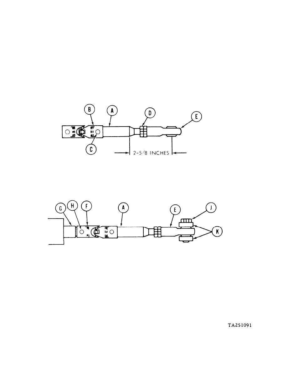
1.
Position shaft (A) in vise and, install universal joint (B) on shaft (A) with holes alined.
Using hammer and punch, install new pin (C) through universal joint (B) and shaft (A).
2.
Using 9/16 inch wrench, install jamnut (D) onto shaft (A).
3.
Install rod end (E) on shaft (A) until center of rod end is 2-5/8 inch from rod (A). Move
jamnut (D) tight against rod end (E).
4.
Using torque wrench and 9/16 inch crow foot, tighten nut (D) against rod end (E) to 190-
195 lb-in (21-22 N .m).
Take shaft (A) and universal joint (F) assembly out of vise. Position universal joint to
5.
rod (G) with holes alined. Using hammer, install new pin (H).
6.
Using 9/16 inch wrench, install screw (J) through bracket (K) and rod end (E). Using
torque wrench and 9/16 inch crow foot, tighten nut (J) to 190-195 lb-in (21-22 N. m).
7.
Adjust shifting linkage (TM 5-5420-202-20).
8.
Install right fuel tank (page 4-17).
End of Task
